PIC Microcontroller Assembly – Fibonacci
PIC 8-bit Microcontroller Assembly
I’m currently working on a project that I need a basic micro-controller for. I’m exploring potential options, and have some PIC chips on hand that I’d like to make use of so I’m considering using a PIC12F629, by Microchip.com. I’ve found the Microchip documentation and community to be quite helpful in getting started. It’s as simple as:
- Download & install MP Lab X IDE: http://www.microchip.com/mplab/mplab-x-ide
- Download & install an XC compiler: http://www.microchip.com/mplab/compilers
- Peruse the PIC12F69 documentation: http://ww1.microchip.com/downloads/en/devicedoc/41190c.pdf
- Read Page 9, 10 (Memory layout)
- Read Page 21, 22 (I/O Pin config)
- Read Page 71 (Instruction Set Summary)
- Refer to Page 72 (Instruction Table)
I’m interested in understanding the lowest level operation of the chip, so I’ve started with writing assembly instead of C. Here is a short and simple implementation of a Fibonacci sequence generator. Since this is an 8-bit chip, the maximum number I’m able to represent is 255, but for convenience of detecting the end of the generator, I end on the 16th step, which also demonstrates the 8-bit overflow.
; PIC 12F629 Register Addresses
#define INDF	0x00
#define STATUS	0x03
#define RP0	0x05	; STATUS<RP0> bit selects the bank
#define FSR	0x04
#define GPIO	0x05	; bank 0
#define TRISIO	0x05	; bank 1

; Global Variables
#define TMP1	0x31
#define TMP2	0x32
#define FIB	0x20	; fibonacci seq array

RES_VECT  CODE    0x0000            ; processor reset vector
    GOTO    START                   ; go to beginning of program

; TODO ADD INTERRUPTS HERE IF USED

MAIN_PROG CODE                      ; let linker place main program


START
    bcf	    STATUS, RP0		; select Bank 0

    ; Build the fibonacci sequence in a memory block
    movlw   0x20    ; start at 0x20
    movwf   FSR	    ; set the indirect addressing address

    ; Initialize sequence with 0,1
    movlw   0x00    ; F_0
    movwf   TMP1    ; store it in working var
    movwf   INDF    ; store it in memory block
    incf    FSR	    ; increment the File Select Register

    movlw   0x01    ; F_1
    movwf   TMP2    ; store it in working var
    movwf   INDF    ; store it in memory block
    incf    FSR;    ; increment the File Select Register

    ; Continue the sequence from F_2 on
NEXT
    ; Add the two last numbers
    movf    TMP1,0  ; W = TMP1
    addwf   TMP2,0  ; W = W + TMP2
    movwf   INDF    ; store W in data block at FSR

    ; update TMP1 and TMP2.. .tmp1=tmp2, tmp2=W
    movf    TMP2,0  ; W = TMP2
    movwf   TMP1    ; TMP1 = W
    movf    INDF,0  ; W = Value at FSR
    movwf   TMP2    ; TMP2 = W

    incf    FSR	    ; increment the File Select Register
    btfss   FSR, 4  ; skip goto when bit 4 of FSR is 1, eg FSR = 0bx1xxxx
    goto    NEXT

    END
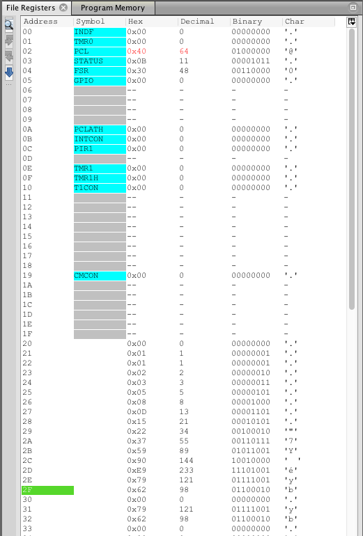
Here is a screenshot of the memory management tool in the MP Lab IDE’s simiulator:
Surely there are easier, more efficient, and/or more compact ways of writing this generator, but this is my naïve first attempt.

Why did you terminate by checking bit 4 of FSR?
Any significance?
btfss FSR, 4 ; skip goto when bit 4 of FSR is 1, eg FSR = 0bx1xxxx
As mentioned, the PIC 12F629, is an 8-bit chip, which means the ALU (https://en.wikipedia.org/wiki/Arithmetic_logic_unit) can only support results of up to decimal 255 before overflowing.
I know that the 15th and 16th steps of the Fibonacci sequence are 377 and 610 respectively. The ALU addition operation overflows, and results in 121 and 98 in memory addresses 0x2E and 0x2F respectively.
I used btfss FSR, 4 as a very simple way to terminate the loop. When FSR reaches a value of 16 (representing the 16th iteration), btfss will skip the following line (the goto NEXT).